Decoding Control Relay Diagrams: A Comprehensive Guide
Ever looked at an electrical diagram and felt lost in a maze of symbols? Control relays, those unsung heroes of automation, are often represented by cryptic shapes and lines. But fear not, for this guide will illuminate the world of control relay schematic symbols, transforming them from enigmatic squiggles into understandable tools.
Understanding these symbols is like learning the language of electrical control systems. They are the shorthand used by engineers to communicate complex circuit functions. From simple on/off switching to sophisticated control logic, relay diagrams provide a visual roadmap of how electricity flows and controls actions.
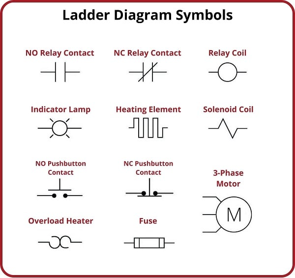
Control relay schematic symbols represent more than just physical components; they embody the logic of the circuit. Each symbol, with its unique shape and accompanying labels, tells a story about the relay's function, its connections, and its role in the overall system. Mastering these symbols is key to designing, troubleshooting, and maintaining electrical control systems efficiently.
The history of relay schematic symbols is intertwined with the development of electrical engineering itself. As circuits became more complex, the need for a standardized visual language emerged. Over time, conventions were established, leading to the symbols we use today. These symbols have evolved to become internationally recognized, facilitating communication and collaboration among engineers worldwide.
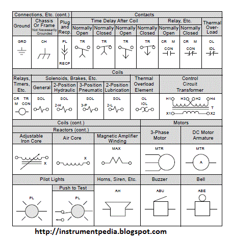
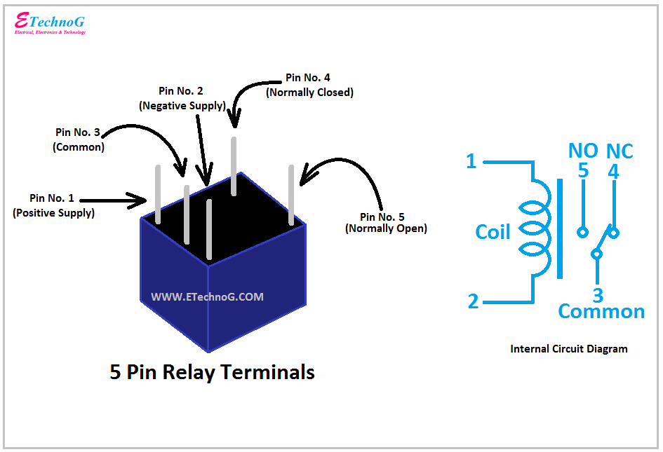
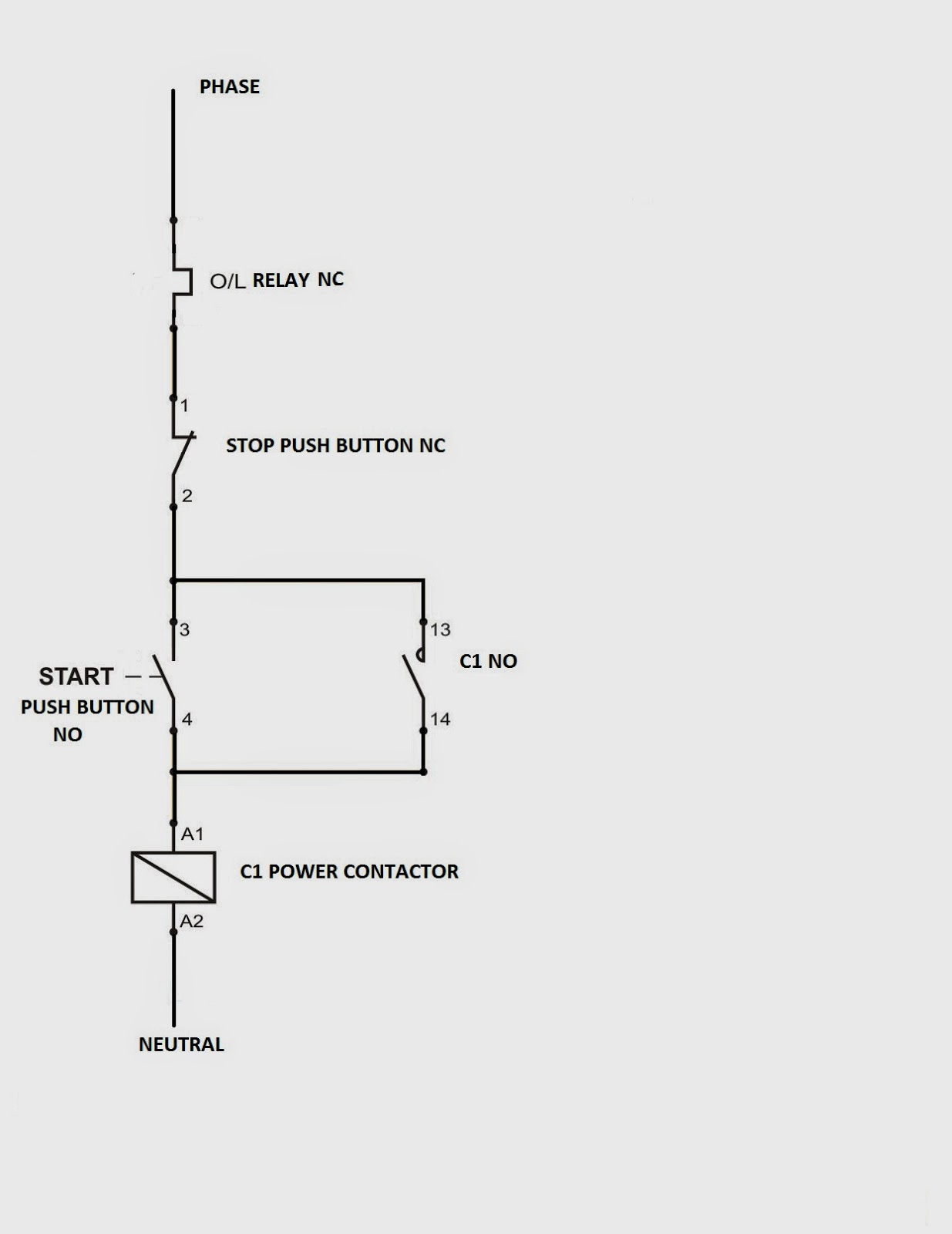
Understanding the diagrammatic representation of a relay's normally open (NO) and normally closed (NC) contacts is fundamental. These designations indicate the state of the contacts when the relay is de-energized. When the relay coil is energized, the NO contacts close, completing a circuit, while the NC contacts open, breaking a circuit. This simple switching action forms the basis of relay-based control logic.
One benefit of using relay diagrams is their ability to simplify complex circuits. By abstracting away the physical details of the components, the diagrams focus on the functional relationships between them. This makes it easier to analyze and understand the overall operation of the system.
Another advantage is the ease of troubleshooting. A well-drawn relay diagram allows technicians to quickly identify faulty components or wiring errors. This saves valuable time and resources during maintenance and repair operations.
Furthermore, using standard relay symbols promotes clear communication among engineers and technicians. This shared language minimizes the risk of misinterpretations and errors during design, installation, and maintenance.
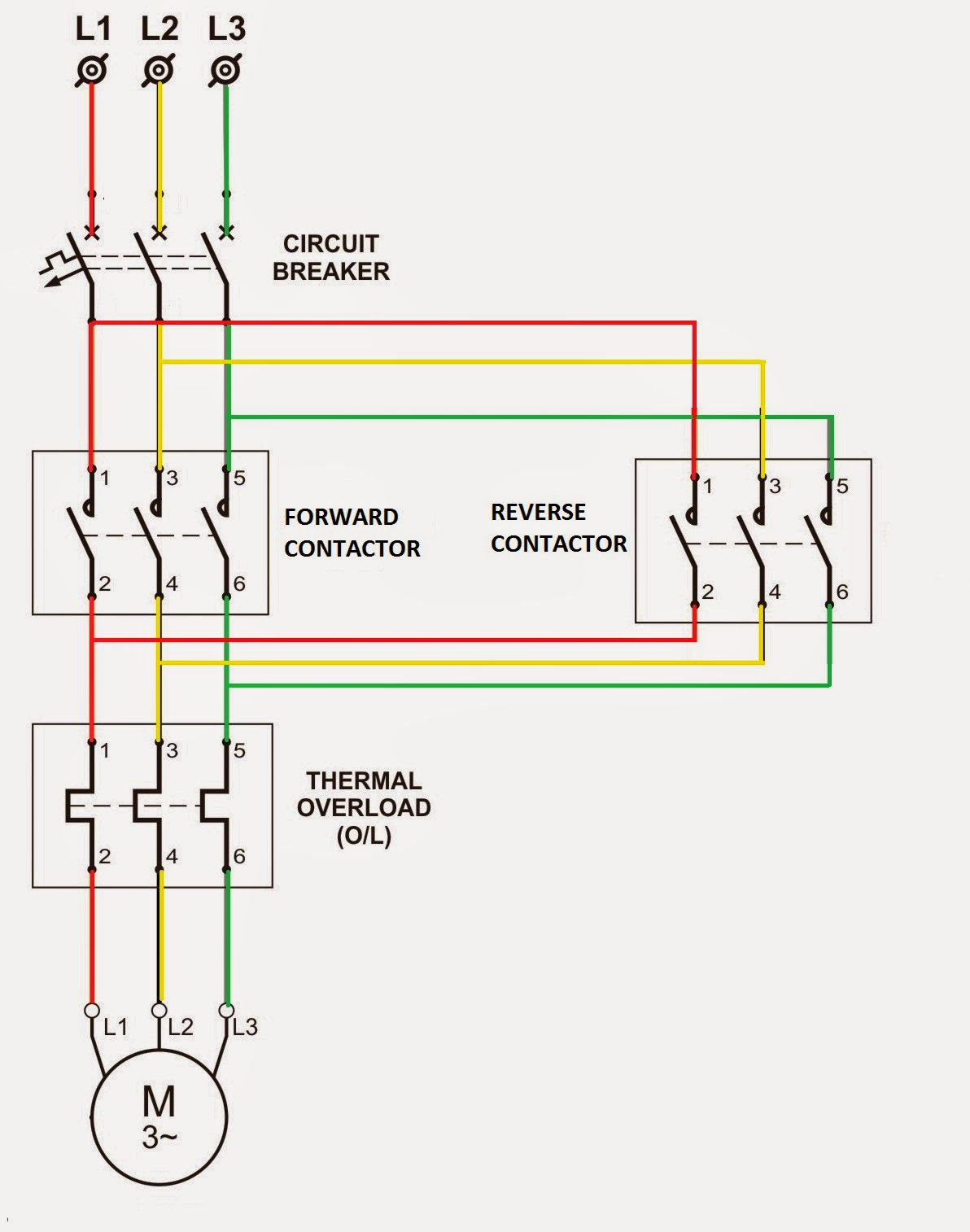
A practical example is a simple motor control circuit. The relay diagram would show the motor starter coil connected to the relay contacts. When the relay is energized, the contacts close, supplying power to the motor starter and starting the motor. When the relay is de-energized, the contacts open, stopping the motor.
Another example is a lighting control system where a relay is used to switch a bank of lights on or off based on a sensor input. The relay diagram would illustrate the connections between the sensor, the relay, and the lights, providing a clear visual representation of the control logic.
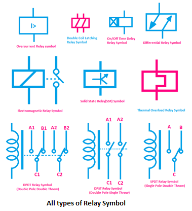
A common challenge in interpreting relay diagrams is understanding the different types of relay symbols. There are variations in how relays are represented depending on the specific application and industry standards. Familiarizing oneself with these variations is crucial for accurate interpretation.
Advantages and Disadvantages of Using Relay Schematic Symbols
| Advantages | Disadvantages |
|---|---|
| Simplified circuit representation | Requires knowledge of symbols |
| Ease of troubleshooting | Can be complex for large systems |
| Clear communication | Variations in symbols can cause confusion |
Best Practices for using Relay Symbols: 1. Use standard symbols whenever possible. 2. Label all components and connections clearly. 3. Keep the diagram organized and easy to read. 4. Use consistent line styles and thicknesses. 5. Document any deviations from standard symbols.
Frequently Asked Questions: 1. What does NO stand for? (Normally Open) 2. What does NC stand for? (Normally Closed) 3. What is a relay coil? 4. How does a relay work? 5. What are the different types of relays? 6. What are the applications of relays? 7. How do I read a relay diagram? 8. Where can I find resources on relay symbols?
Tips and Tricks: Pay close attention to the labels on the relay symbols. Understand the difference between NO and NC contacts. Use a multimeter to test the relay's functionality.
In conclusion, the world of control relay schematic symbols may seem daunting at first, but with a little effort, it becomes a powerful tool for understanding and controlling electrical systems. These symbols are the key to unlocking the secrets of complex circuits, allowing us to design, troubleshoot, and maintain automated systems effectively. By embracing the language of relay diagrams, we gain a deeper appreciation for the intricate workings of the electrical world and empower ourselves to harness its potential. This understanding allows engineers and technicians to create more reliable, efficient, and sophisticated control systems, contributing to advancements across various industries. Take the time to familiarize yourself with these symbols, and you'll open a door to a world of electrical innovation. From simple household appliances to complex industrial automation, control relays are the silent workhorses of modern technology. Understanding their schematic representation empowers us to control and shape the world around us.
The curious case of the old english 104 a journey through typography
The enduring allure of rose tattoo sketches
Unlocking the chevy malibu color spectrum a deep dive
