Unlocking Hydraulic Systems: A Guide to Diagram Symbols
Ever wondered how complex machinery like excavators or airplane landing gear operate so smoothly? The answer often lies within their intricate hydraulic systems. These systems, powered by pressurized fluid, rely on a standardized visual language: hydraulic system diagram symbols. Understanding these symbols is crucial for anyone involved in designing, maintaining, or troubleshooting hydraulic equipment.
Hydraulic system diagrams provide a blueprint for these powerful systems. They serve as the common language between engineers, technicians, and operators. Without a standardized set of symbols, deciphering the intricacies of a hydraulic circuit would be a daunting task. Imagine trying to understand a complex electrical circuit without knowing what resistors or capacitors represent. Similarly, hydraulic symbols provide the visual key to unlocking the functionality of these fluid-powered systems.
The history of hydraulic system diagram symbols is intertwined with the development of hydraulic technology itself. As hydraulic systems became more complex, the need for a standardized symbolic representation became evident. Early diagrams were often rudimentary, but over time, organizations like ISO (International Organization for Standardization) developed a comprehensive set of symbols, ensuring clarity and consistency across industries.
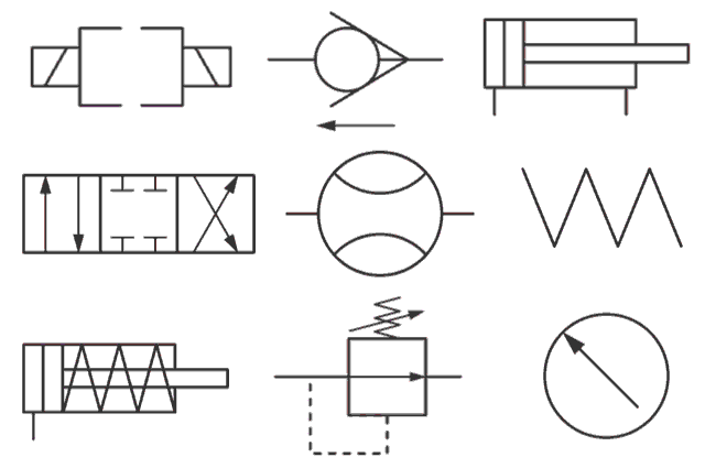
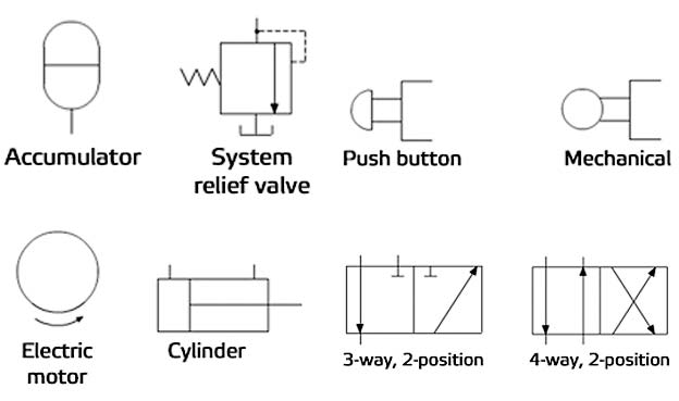
The importance of standardized hydraulic schematic symbols cannot be overstated. These symbols represent various components like pumps, valves, actuators, and filters. They depict the flow of hydraulic fluid, the direction of control signals, and the interconnections between different parts of the system. This standardized representation facilitates effective communication and collaboration among professionals, reducing the risk of misinterpretations and errors.
One of the main issues related to hydraulic representations is the potential for misinterpretation if the diagrams are not created or read correctly. A misplaced symbol or an incorrect connection line can lead to malfunctioning equipment or even safety hazards. This highlights the importance of proper training and adherence to standardized practices when working with hydraulic system diagrams.
A simple example is the symbol for a directional control valve. This valve determines the path of hydraulic fluid flow. Different variations of the symbol indicate the number of positions and flow paths within the valve. Understanding this symbol allows technicians to quickly identify the valve's function and how it controls the hydraulic circuit.
One benefit of using hydraulic diagram symbols is improved troubleshooting. By visually tracing the flow of fluid and the operation of components, technicians can quickly pinpoint the source of a problem. Another benefit is streamlined design. Engineers can use these symbols to efficiently design and optimize hydraulic circuits, ensuring efficient power transmission and control. Furthermore, clear communication is facilitated, as everyone involved in the project can readily understand the system's functionality through the standardized symbols.
An action plan for implementing hydraulic system diagrams in a project involves first defining the system requirements, then creating a schematic using standardized symbols, followed by verification and validation of the design. Successful examples can be found in various industries, from automotive manufacturing to aerospace engineering, where hydraulic systems are essential for precise control and power transmission.
Advantages and Disadvantages of Standardized Hydraulic Symbols
| Advantages | Disadvantages |
|---|---|
| Clear Communication | Requires Training |
| Efficient Troubleshooting | Potential for Misinterpretation |
| Streamlined Design | Constant Updates to Standards |
Best practices include using the latest ISO standards, ensuring clear labeling and annotations on the diagram, and maintaining consistency in symbol usage throughout the project.
Real-world examples include the hydraulic systems in construction equipment, aircraft landing gear, and industrial presses. Each system utilizes standardized symbols to represent its unique configuration of pumps, valves, and actuators.
A common challenge is keeping up with evolving standards. Regular training and access to updated resources are crucial for ensuring accurate interpretation and application of hydraulic system diagram symbols.
Frequently asked questions about hydraulic symbols often relate to specific component representation, interpretation of complex circuits, and the latest ISO standards.
A tip for understanding hydraulic diagrams is to follow the flow of fluid through the circuit, tracing the symbols from the pump to the actuators. This helps visualize the system's operation and understand the role of each component.
In conclusion, hydraulic system diagram symbols are the essential language of fluid power. They provide a standardized visual representation that facilitates communication, design, and troubleshooting. From the history of their development to their critical role in complex machinery, understanding these symbols is paramount for anyone involved in the world of hydraulics. By mastering this visual language, we can unlock the full potential of hydraulic systems, ensuring their efficient and safe operation. Embracing the standardized representation offered by these symbols empowers us to design, maintain, and troubleshoot hydraulic systems with confidence and precision, ultimately driving innovation and efficiency in a wide range of industries. Take the time to learn and apply these symbols correctly – it's an investment that will pay dividends in the long run.
Transform your walls behr masonry paint guide
Navigating comfort your guide to heating and air in columbus ohio
The enduring allure of long hair anime boys why we cant resist


