Unlocking the Secrets of PIR Sensor Circuitry: Schematics Decoded
Ever wondered how that motion-sensing light knows you're there? The answer lies within the fascinating realm of PIR sensor circuitry, and more specifically, the PIR sensor schematic diagram. These diagrams, like treasure maps for electronics enthusiasts, hold the key to understanding how these ubiquitous sensors detect movement and trigger actions.
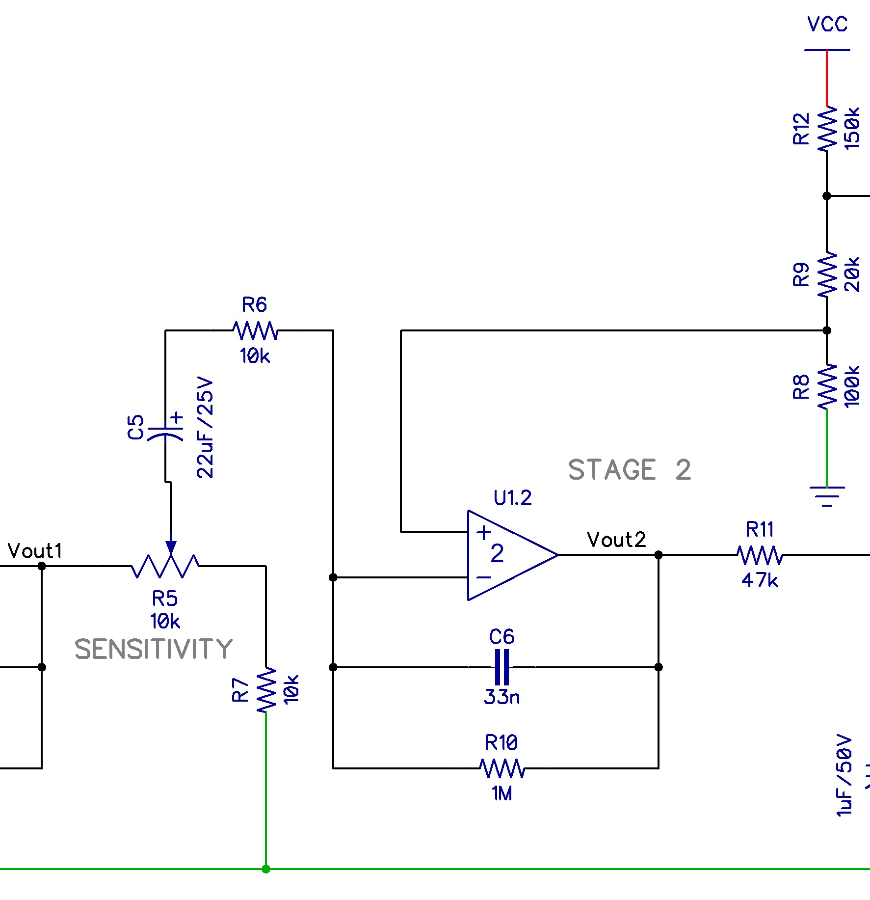
A PIR sensor, or Passive Infrared sensor, is a marvel of modern electronics, silently watching for changes in infrared radiation. Think of it as an electronic eye tuned to the heat signatures of moving objects. But how does this "eye" translate warmth into electrical signals? That’s where the schematic comes in. A PIR sensor schematic diagram is a visual representation of the sensor's internal components and their connections, revealing the intricate dance of electrons that brings these sensors to life.
The history of PIR sensor technology is intertwined with the development of infrared detection itself. Early versions were bulky and expensive, primarily used in military applications. Over time, advancements in microelectronics allowed for miniaturization and cost reduction, opening up a world of possibilities for commercial and consumer use. Today, PIR sensors are everywhere, from security systems and automatic lighting to interactive toys and even touchless faucets.
The importance of understanding the PIR sensor schematic diagram cannot be overstated. It empowers you to troubleshoot malfunctions, modify existing circuits, or even design your own custom applications. A common issue with PIR sensors is false triggering. By examining the schematic, you can pinpoint potential causes, like incorrect component values or improper wiring. This knowledge saves time and frustration, transforming you from a passive user to an active problem-solver.
A typical PIR sensor schematic includes components like the pyroelectric sensor, operational amplifiers, comparators, and timing circuits. The pyroelectric sensor is the heart of the device, converting infrared radiation into electrical signals. These signals are then amplified, processed, and compared to a threshold by the other components, ultimately triggering an output when motion is detected. A simple example is a motion-activated light. When the PIR sensor detects movement, the output signal activates a relay, switching the light on.
One benefit of understanding PIR sensor circuitry is the ability to customize sensitivity. By adjusting component values in the schematic, you can fine-tune the sensor's responsiveness to motion, preventing false triggers from small animals or air currents. Another advantage is extending the activation time. By modifying the timing circuit, you can keep a light on for a longer period after motion is detected.
Troubleshooting a malfunctioning PIR sensor often begins with visually inspecting the schematic diagram. Check for loose connections, damaged components, or incorrect wiring. A multimeter can be used to test component values and verify signal flow through the circuit.
Several websites and forums dedicated to electronics offer valuable resources on PIR sensor schematics. These platforms often feature detailed diagrams, explanations, and community discussions that can help you deepen your understanding.
Advantages and Disadvantages of Working with PIR Sensor Schematics
| Advantages | Disadvantages |
|---|---|
| Customization and flexibility in design | Requires basic electronics knowledge |
| Troubleshooting and repair capabilities | Can be complex for beginners |
| Deeper understanding of sensor operation | Risk of damaging components if not careful |
Five best practices for working with PIR sensor schematics include: 1) Always double-check component values before soldering. 2) Use a proper soldering iron and technique to avoid damaging the circuit board. 3) Test the circuit incrementally as you build it. 4) Ensure proper grounding to prevent interference. 5) Enclose the circuit in a protective housing to shield it from environmental factors.
Real-world examples of PIR sensor applications include: 1) Security systems. 2) Automatic lighting. 3) Occupancy sensors for energy saving. 4) Touchless faucets. 5) Interactive toys.
Frequently asked questions: 1) What is a PIR sensor? 2) How does a PIR sensor work? 3) What are the common applications of PIR sensors? 4) How do I troubleshoot a PIR sensor? 5) Where can I find PIR sensor schematics? 6) How can I adjust the sensitivity of a PIR sensor? 7) How can I extend the activation time of a PIR sensor? 8) What are the key components of a PIR sensor circuit?
Tips and tricks for working with PIR sensor schematics: Use a magnifying glass to examine small components. Keep a well-organized workspace to avoid losing components. Refer to datasheets for detailed component specifications. Practice soldering on scrap circuit boards before working on your project.
In conclusion, the PIR sensor schematic diagram is more than just a collection of lines and symbols; it's a gateway to understanding a powerful and versatile technology. By delving into the intricacies of these diagrams, you unlock the potential to customize, troubleshoot, and even design your own PIR sensor applications. From enhancing home security to creating interactive installations, the possibilities are limited only by your imagination. Embrace the power of the schematic, and explore the fascinating world of PIR sensor technology today! This understanding can empower you to create smarter, more responsive environments, whether you're building a sophisticated security system or simply automating your home lighting. So, take the plunge and discover the endless possibilities that await within the world of PIR sensor circuitry.
Nfl draft shakeup who were the big winners last night
Milwaukee cars and trucks on craigslist your guide
Deciphering the dreaded p0157 obdii code oxygen sensor insights


