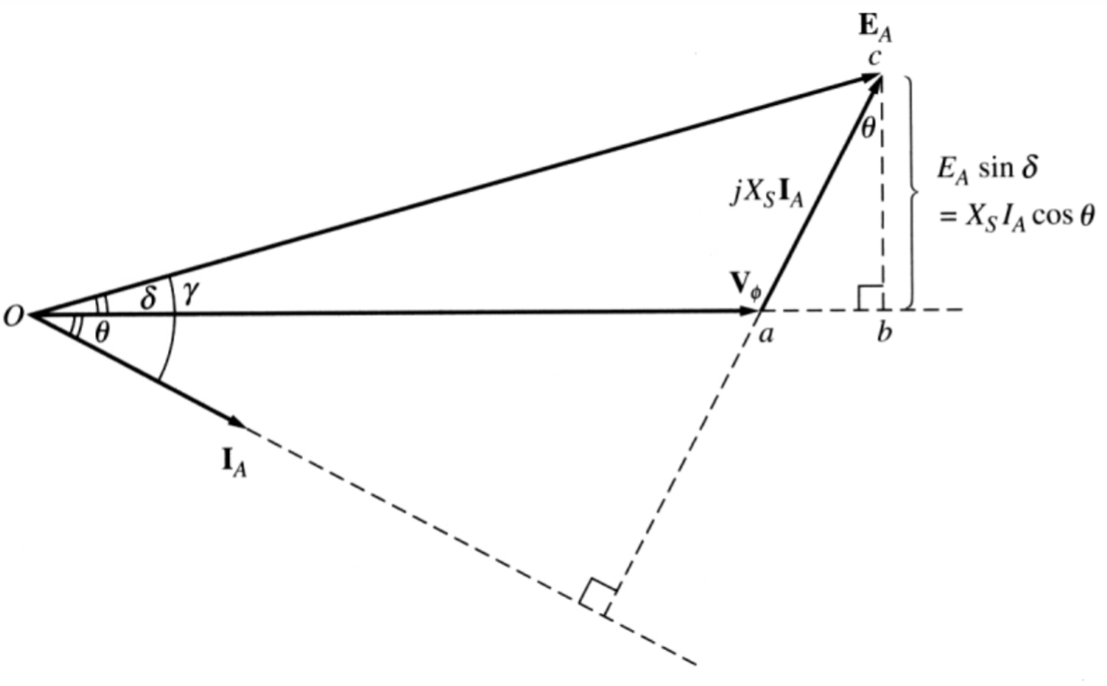
Unlocking the Secrets of Synchronous Generator Phasor Diagrams
Ever wondered how the humming power grid stays balanced and delivers electricity to your home? It's a complex dance of voltages, currents, and magnetic fields, orchestrated by synchronous generators. And one of the most elegant tools for understanding this intricate choreography is the synchronous generator phasor diagram. These diagrams aren't just abstract squiggles on a page; they're powerful visual keys that unlock the secrets of power system operation.
Synchronous generator phasor diagrams represent the alternating voltages and currents within the generator as rotating vectors, or phasors. They provide a snapshot of the generator's internal electrical state at a particular moment in time. By understanding these diagrams, engineers can analyze and predict the behavior of the generator under various operating conditions. This knowledge is essential for maintaining stability, efficiency, and reliability in the power system.
From the early days of AC power systems, graphical representations have been vital for understanding the complex relationships between voltage and current. The concept of phasors emerged as a powerful tool to simplify the analysis of sinusoidal quantities. As synchronous generators became the backbone of power generation, phasor diagrams evolved to specifically address their unique operating characteristics, playing a crucial role in the design, operation, and troubleshooting of these machines.
A synchronous generator’s phasor diagram is constructed by representing the generator's internal induced voltage (Ea), the terminal voltage (Vt), the armature current (Ia), and the various voltage drops associated with armature resistance (Ra) and synchronous reactance (Xs). The relative positions and magnitudes of these phasors reveal critical information about the generator's operating state, including the power factor, the load angle, and the level of excitation.
The significance of the synchronous generator phasor diagram cannot be overstated. It allows engineers to visualize the complex interplay of electrical quantities within the generator. This visualization facilitates the analysis of various operating scenarios, such as changes in load, variations in excitation, and the impact of faults. By understanding these diagrams, we can optimize generator performance, ensure system stability, and prevent costly failures.
One of the main issues related to understanding phasor diagrams is grasping the concept of rotating vectors and their relationship to sinusoidal waveforms. It’s crucial to remember that the phasor represents the magnitude and phase angle of the sinusoidal quantity. Another challenge is correctly identifying and accounting for the different voltage drops within the generator, particularly the voltage drop across the synchronous reactance, which is a key factor in determining the generator's stability.
Benefit 1: Predicting Generator Behavior Under Varying Loads. Example: By analyzing the phasor diagram, engineers can predict how the generator's terminal voltage and current will change as the load increases or decreases.
Benefit 2: Optimizing Generator Excitation. Example: The phasor diagram helps determine the optimal excitation level to maintain the desired terminal voltage and power factor.
Benefit 3: Analyzing the Impact of Faults. Example: Phasor diagrams can be used to simulate the effects of faults on the generator and the power system, enabling engineers to develop protective strategies.
Advantages and Disadvantages of Using Phasor Diagrams
| Advantages | Disadvantages |
|---|---|
| Simplified analysis of complex AC circuits | Limited to steady-state analysis |
| Visual representation of voltage and current relationships | Requires understanding of phasor concepts |
| Facilitates understanding of generator operation | Can be complex for large systems |
Best Practice 1: Always ensure that the phasor diagram is drawn to scale to accurately represent the magnitudes of the voltages and currents.
Best Practice 2: Clearly label all phasors and angles to avoid confusion.
Best Practice 3: Use a consistent reference phasor (usually the terminal voltage) for all diagrams.
Best Practice 4: Consider the effects of saturation on the synchronous reactance, especially at higher excitation levels.
Best Practice 5: Validate the phasor diagram with actual measurements whenever possible.
FAQ 1: What is a phasor? A phasor is a rotating vector that represents a sinusoidal quantity.
FAQ 2: What is synchronous reactance? Synchronous reactance represents the magnetic flux linkage between the stator and rotor of the synchronous generator.
FAQ 3: What is the load angle? The load angle is the angle between the internal induced voltage (Ea) and the terminal voltage (Vt).
FAQ 4: What is the significance of the power factor? The power factor indicates the relationship between the real power and the apparent power in the circuit.
FAQ 5: How does excitation affect the phasor diagram? Increasing excitation increases the magnitude of the internal induced voltage (Ea).
FAQ 6: What is the difference between a lagging and leading power factor? A lagging power factor indicates that the current lags behind the voltage, while a leading power factor indicates that the current leads the voltage.
FAQ 7: How are phasor diagrams used in power system analysis? Phasor diagrams are used to analyze the steady-state behavior of power systems.
FAQ 8: What are some common mistakes to avoid when constructing phasor diagrams? Common mistakes include not drawing the diagram to scale, incorrectly labeling the phasors, and not considering the effects of saturation.
In conclusion, the synchronous generator phasor diagram is a powerful tool for understanding and analyzing the operation of these crucial machines. From optimizing generator performance to ensuring power system stability, these diagrams offer valuable insights into the complex interplay of electrical quantities. By mastering the art of phasor diagram interpretation, engineers can unlock the secrets of the power grid and ensure a reliable and efficient flow of electricity to the world. Take the time to delve deeper into this fascinating subject, explore further resources, and harness the power of phasor diagrams to enhance your understanding of synchronous generators and the power systems they drive.
Color me bold unleashing the power of aesthetic red blue yellow backgrounds
Tiktok verification symbol copying and pasting unveiling the truth
Amazon vacuum pump kits suck it up get informed


